SO2. Define and implement execution of cognitive guidance and control algorithms through cooperative formations and manoeuvres in order to ensure diver monitoring, uninterrupted mission progress, execution of compliant cognitive actions, and human-machine interaction

SO2.a. Develop and implement cooperative control and formation keeping algorithms with a diver as a part of the formation.
This sub-objective is considered fully completed and was tested during final validation trials. The cooperative control and formation keeping algorithms consist of a surface vehicle and underwater vehicle controllers. The controllers employ different strategies with the surface exercising relaxed tracking and underwater exercising an extended version of exact tracking.
Diver-BUDDY-USV formation keeping control
The BUDDY vehicle, in addition to diver tracking, performs a range of different tasks, e.g. lawn-mower, carry-to-boat. This task combination makes the resulting BUDDY movement challenging for estimation and exact tracking algorithms. However, the surface vehicle, in the CADDY concept, needs only to be near the agents to improve acoustic communications and localization aiding. Without exact tracking requirements, relaxed tracking can be achieved using artificial potential fields (AFP) to create a safety basin in the vicinity of BUDDY and the diver. The method is scalable to more agents and combining potential functions desired regions for the surface vehicle are created. The vehicle is made to converge naturally into basin regions thus avoiding occupying space directly above the diver or BUDDY. The implemented AFP controller creates a basin (Fig. SO2.1.)
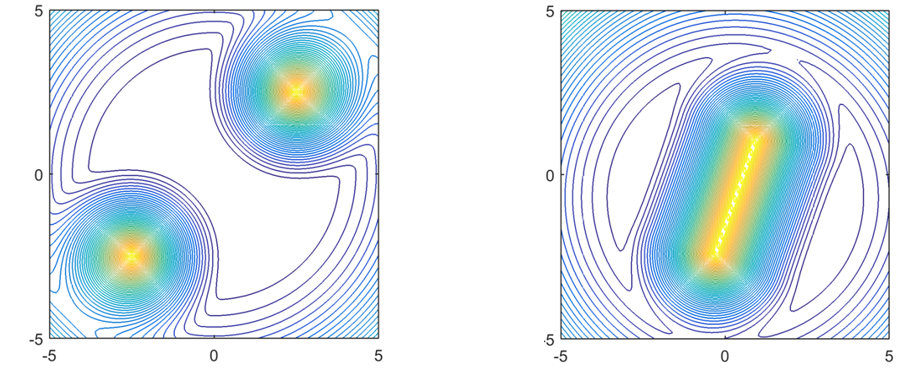
Fig. SO2.1. The artificial potential field (AFP) method used for the Diver-BUDDY-USV formation keeping. (Left) The AFP field for normal distribution of diver and BUDDY with a basin created in the middle between the two agents. (Right) The AFP created by the panel method when diver and BUDDY are close. Two smaller basins are created on the sides for the surface vehicle to converge.
The standard AFP approach generates the field potential on Fig. SO2.1a) which results in a low-potential basin attracting the surface vehicle. The basin has a constant potential resulting in a region–keeping behaviour of the surface vehicle. However, with this approach, when the underwater agents are close, the sum of the potential fields can generate local minima and saddle points, which cause convergence problems with the vehicle. Instead of creating separate potential fields, a single potential connecting two agents is generated as shown in Fig. SO2.1b). This type of potential function is known in fluid mechanics as the panel method.
Diver-BUDDY cooperative control
Contrasting to surface vehicle requirements, the CADDY concept requires exact manoeuvring around the diver prompting for a different approach. Path stabilization, with a circular path around the diver, was chosen as the control strategy for diver tracking, observing and guidance.
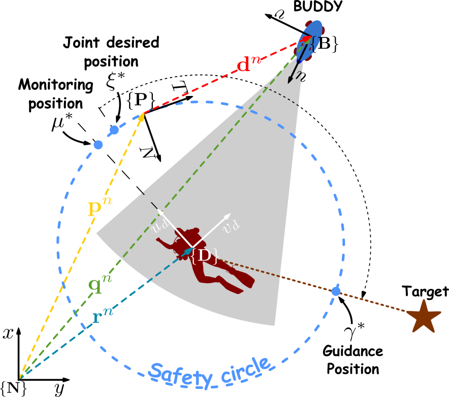
The overall path stabilization concept is shown in Fig. SO2.2. The path is fixed to the diver and diver movements directly affect the path position. BUDDY has to converge on a desired path point by minimizing . Controller parameters are selected to force BUDDY to first converge on the path and only then traverse the path to the desired point. Maintaining the position on the path which is travelling with the diver achieves the tracking objective. The observer objective in general covers different aspects from monitoring the physiological state, posture and diver position. From the controller perspective, observing covers keeping the diver in sonar and camera field of view and on the closest range of the USBL sensor mounted in front of the diver. This requires maintaining constant orientation towards the diver independent on path position. Omni-directional nature of BUDDY allows independent control of heading and position making the task achievable. The best position was selected directly in front of the diver at . Camera and sonar observations from this point are best for partial diver posture estimation. Line-of-sight occlusion between the USBL and acoustic modem by the diver are minimized. Additionally, the diver does not have to rotate towards BUDDY to initiate gesture communication. The drawbacks of positioning directly in front are: a) the diver heading has to be known accurately and b) the diver might find it unnatural to swim directly into BUDDY even if BUDDY backs away. The diver orientation is estimated by the torso mounted diver-net sensor. Finally, guidance has to be achieved without losing the other two objectives.
|
|
|
Fig. SO2.2. The path stabilization concept with a circular path which moves with the diver.
|
Diver approach extension
During trials and additional extension was introduced into the BUDDY guidance, namely, the approach step. The issue with maintaining constant distance to the diver is that some diver slave tasks cannot be executed. Therefore, an intermediate state was introduced providing the ability for the diver to allow approach. Effectively, path movement is suspended and the current BUDDY point is selected for station keeping allowing the diver to approach BUDDY and load objects or retrieve tools from BUDDY. During final validation trials the BUDDY entered this state before go and carry mission was initiated to carry an object placed by the diver to the surface. Effectively, the extension combines the station-keeping capabilities of BUDDY without losing track of the diver.
Experimental results
Extensive results for surface and BUDDY tracking controllers are presented in D4.2, D5.2 and D5.3. Figure below provide only an overview of the concept implementation in real-life scenarios.
Figure below, the surface tracking performance, obtained on field-trails, is shown with the absolute distance between the surface and underwater vehicles. The minimum and maximum distances form a donut around the underwater vehicle when converted into 2D. As seen on the error plot, the vehicle occasionally lags behind, however, it never approaches above or too close to other agents.
|
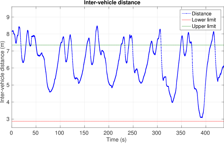
a) The distance between two agents.
|
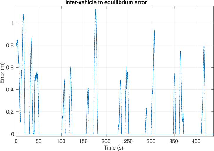
b) The tracking error relative to the donut shaped equilibrium zone.
|
|
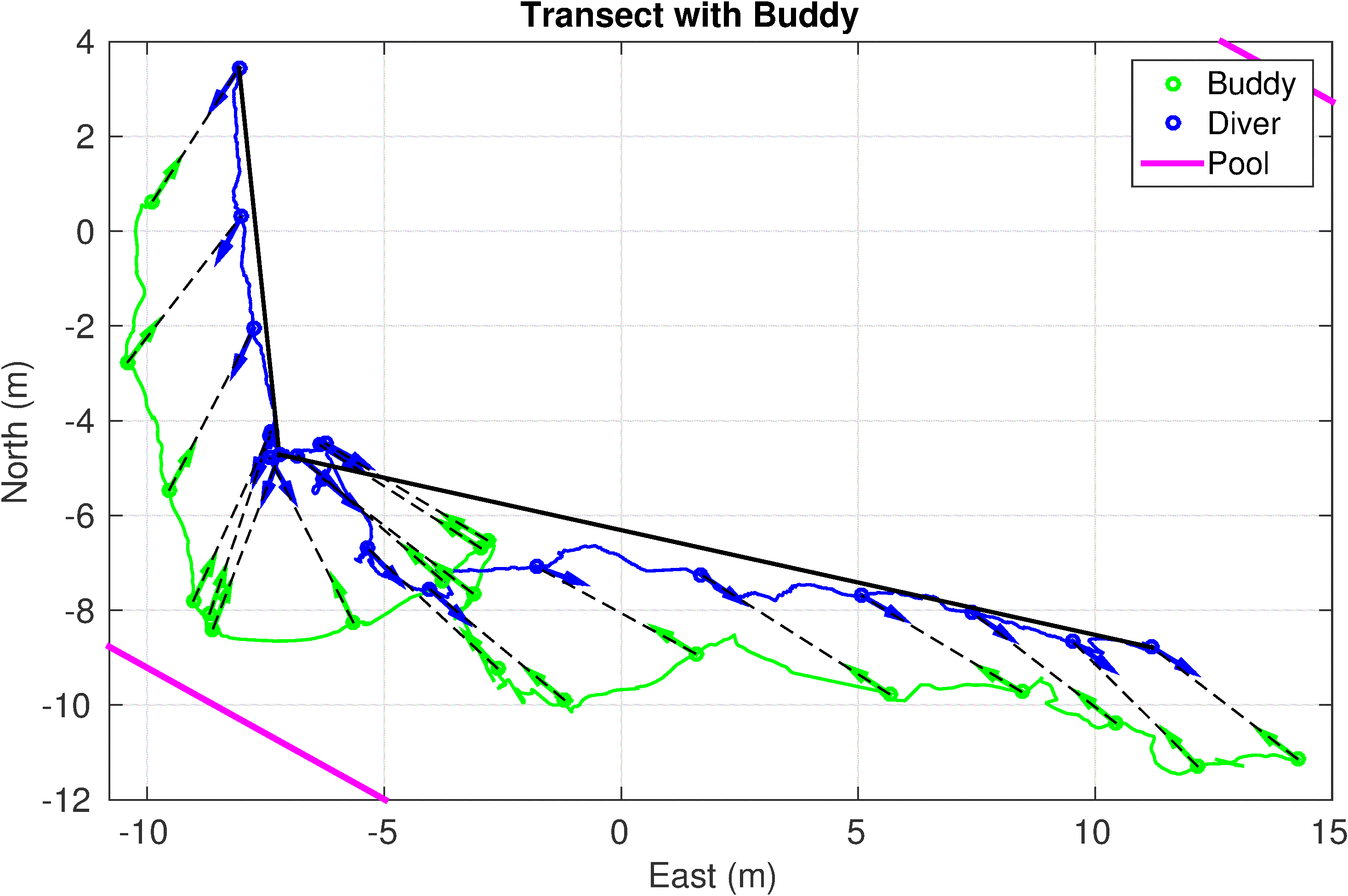
c) Diver movement along the transect. Observe that there is a heading dependent offset between diver actual course and heading.
|
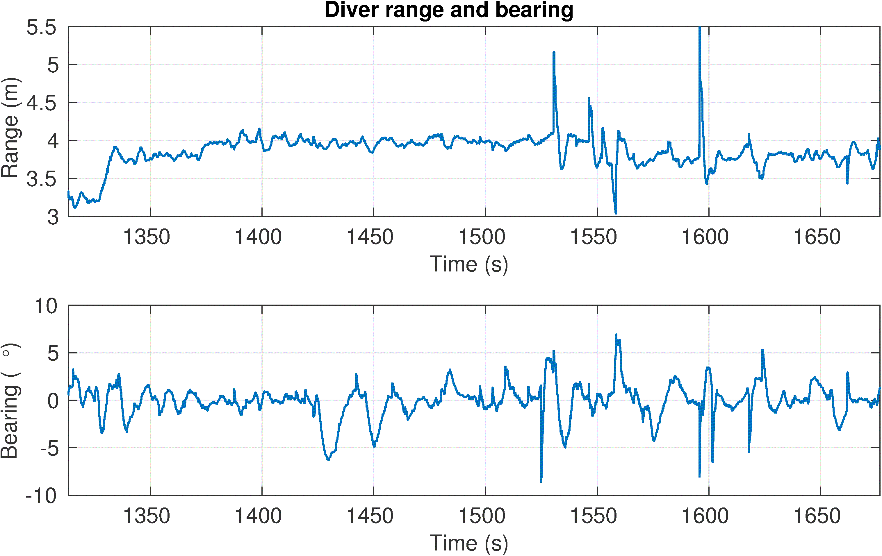
d) The range and bearing plot. The desired range from the diver is changed during testing to find the best position at 3.8m.
|
|
Fig. SO2.3. Results of the overall cooperative and formation control.
|
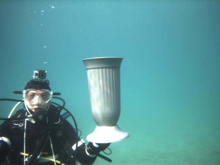
Fig. SO2.3.c shows the tracking performance and the aforementioned heading offset during straight line movement. Observe that BUDDY is always in front of the estimated diver orientation but that the diver appears to be moving sideways. Actually, the diver is moving almost parallel to the transect line but the un-calibrated offset makes BUDDY observe the diver from the side (Fig. SO2.4.). During this experiment the heading was estimated purely by the diver-net sensor. The desired range is adjusted to 4m at which distance the camera point-cloud was still able to estimate range and bearing to the diver but not the diver heading. The gesture recognition worked at this distance but faster recognition was achieved at smaller distance from 2.5-3 m where the visibility is good (figure S02.5.). The working range of the sonar is good from up to 10m but the optimal range is between 3-6m. Below 3m the camera provides better estimates as the diver occupies the complete narrow field of the sonar.
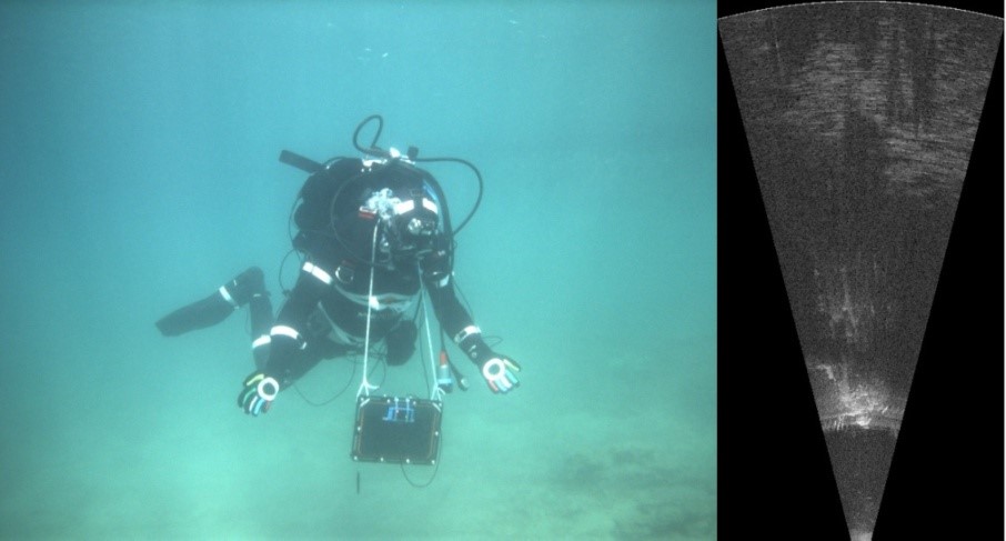
Fig. SO2.4. Video and sonar snapshot from the tracking experiment shown above.
a) b)
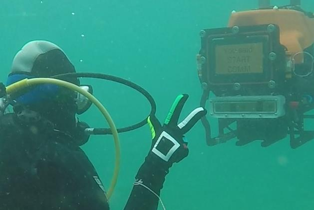
Fig. SO2.5. Additional photos from validation experiments: a) The diver showing gestures to Buddy at 2.5m distance, and b) Diver showing the object found and to be mounted on Buddy before sending it to the surface
The main behaviour of diver-buddy cooperation, e.g. in Figure SO2.3c, consists of three sub-elements: approach, rotation and tracking. Therefore, individual performance of these sub-elements is analysed in separate experiments.
a) approach experiment – BUDDY vehicle starts from a large distance behind the diver, and positions itself in front of the diver without compromising the safety radius.
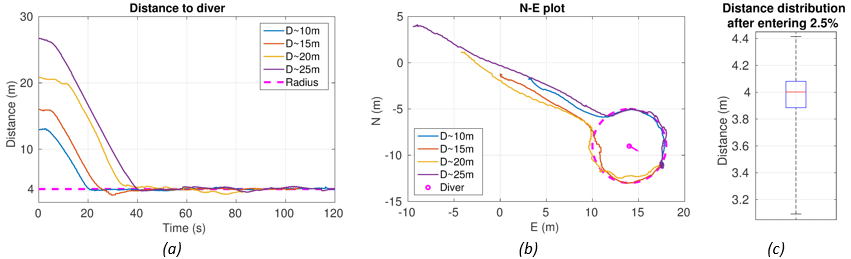
Fig. SO2.6. Field results of the approach experiment: (a) the distance reduction to the safety radius. The distance distribution along the path is shown in (c) and the vehicle trajectory in (b). The box-plot shows the median value with the box between the 25th and 75th percentiles and whiskers showing Min-Max values. Standard positioning controllers without collision detection, would converge directly towards the point causing them to pass through the safety radius
b) rotating experiment – the diver changes orientation while the BUDDY vehicle has to position itself in front of the diver keeping a safe distance at all times.
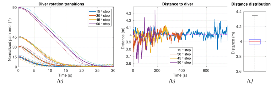
Fig. SO2.7. Forty-eight field results of the “rotating” experiments are shown in the above figures. The normalized path (angular) error is shown in (a). The distance to the diver during transitions and the distance distribution are shown in (b) and (c), respectively.
c) tracking experiment – BUDDY vehicle has to keep distance and orientation relative to the diver, while the diver is moving in the horizontal plane and arbitrarily changing orientation.
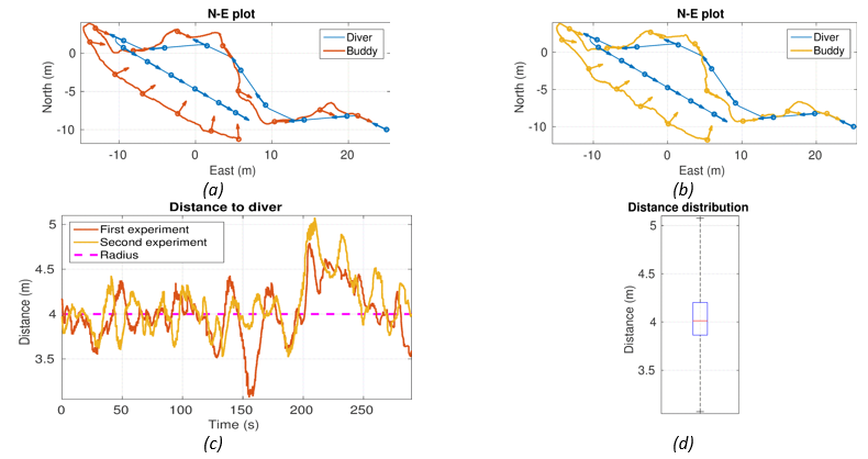
Fig. SO2.8. Field results of two “tracking” experiments with diver moving at 0.2m/s. The North-East plots for each experiment are shown in (a) and (b). Distance to the diver and its distribution are shown in (c) and (d), respectively. Observe that the vehicle adapts to changes in the diver orientation during the zigzag part. In the second part the vehicle begins to overtake the diver. Note that 20 m are needed for the vehicle to start getting in front of the diver. This is attributed to the fact that the maximum achievable sway speed is ≈ 0.3 m/s.
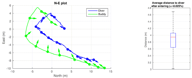
Fig. SO2.9. Field result of “tracking experiment”, specifically, the overtaking part. The North-East plot is shown left and the distance to diver distribution is shown right.
SO2.b. Develop cooperative navigation techniques based on distributed measurements propagated through acoustically delayed sensing network.
Navigation filter using USBL and DVL measurements
With the aim of providing a smooth navigation benefiting from all the sensors an Extended Kalmar Filter (EKF) was developed. This filter works for all the three agents (surface, underwater and diver).
The surface vehicle must estimate the position of the underwater one in order to track it, while the underwater vehicle needs to estimate the position of the surface one in order to use the USBL measurements (range and bearing between vehicles) to infer its own position. Note that bearing and range measurements are used by the filter as separate measurements, so that the variances can be tuned according to the measurement noise.
|
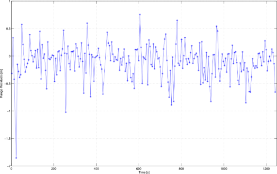
SO2.10. Range residuals on a filter update. Note that the performance is good since these measurements are obtained only approximately once every 6 seconds and the surface vehicle has no extra information regarding the motion of the underwater one being the velocity of the underwater vehicle is very hard to estimate.
|
The state of the filter was defined as , each of these entries is a 2D vector where is the estimated global position , the inertial velocity, the velocity of the current, and the number indices refer to other agents estimates. As updates, the filter accepts GPS, DVL bottom and water track, velocity from thrusters, range and bearing and exchanged position and velocities in the acoustics.
Delays were taken into account by keeping a buffer of previous measurements with their correspondent state and covariance. Moreover, outliers are rejected using a normalized residual validation gate which is then displayed real-time on the console, if a Wi-Fi link to the vehicle is available.
Fig. SO2.10 shows the range residuals. Additional results can be check in CADDY Year 2 report and Nađ et al. (2016).
Maximizing observability by using extremum seeking
|
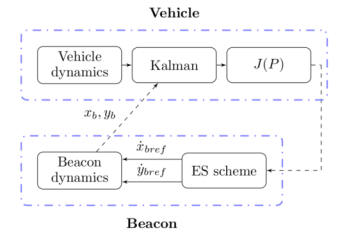
Fig. SO2.11. Extremum seeking scheme
|
Good underwater localization is of utmost importance for successful execution of all CADDY scenarios and therefore USBL systems are used to achieve that. Cheaper alternative is to use range only measurements. In such case unmanned surface vehicle (USV) is trying to execute trajectories informative enough in order to enhance observability of an underwater agent which navigates itself by using only range measurements acquired by acoustic modems. Extremum Seeking scheme is particularly interesting for underwater applications due to limited bandwidth of acoustic communications. For more detailed information check Mandic et al. (2016). The proposed concept is shown in Fig. SO2.11.
In this setup, the mobile beacon moves in order to maximize the information and in the meanwhile sends its position , obtained from GPS, to the vehicle’s Kalman filter used for navigation. Information generated in the navigation filter is then used to calculate cost function value J which gives a measure of observability. Current cost value is then sent to mobile beacon which tries to minimize it online by using Extremum Seeking scheme which steers the mobile beacon towards the minimum of cost function.
|
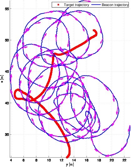
Fig. SO2.12. Target and beacon trajectory
|
Extremum Seeking is not a model based approach so it can be easily deployed on different types of vehicles. That can be particularly interesting in cases when model is difficult or impossible to obtain, such as agent to track is a human diver. Another great advantage of Extremum Seeking is the fact that constant disturbances acting on vehicle, i.e. gravity, buoyancy or currents, are automatically compensated by the Extremum Seeking control loop. Furthermore, the proposed algorithm does not require knowledge of the vehicle’s trajectory in advance.
A large number of trials were successfully performed, showing its robustness. One of the trials included an experimental setup consisting of two autonomous underwater vehicles: Girona 500 and Sparus II (by Underwater Robotics Laboratory of the University of Girona, Spain). Girona 500 vehicle acted as the beacon vehicle, while Sparus II was the target vehicle. The beacon’s position and velocity vectors and the cost were exchanged over acoustic link. Also, USBL measurements from a stationary mounted USBL were used as ground truth for underwater vehicle position. All the computations were done online, aboard the vehicles. During the experiment the underwater target vehicle executed the trajectory shown in Fig. SO2.12. at the constant depth of 3 meters. The mean communication period was 3.4 s.
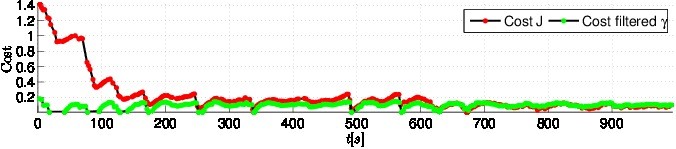
Fig. SO2.13. Observability cost value and filtered cost value during experiment. Initially the cost value is high and by executing the algorithm the cost decreases and stays bounded during the whole experiment, regardless of the target movement.
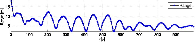
Fig. SO2.14. Range measured on target vehicle. Towards the end it is possible to observe that the range is stabilizing meaning that the circular trajectory around the target is being established.
Purple arrows over the beacon trajectory represent the beacon velocity vector at respective positions. It is immediately visible that the beacon vehicle is executing a circular motion which is known to be observable while tracking the underwater target movement. The observability cost J and the filtered cost γ calculated on the target vehicle are shown in Fig. SO2.13. The range between the vehicles is shown in Fig. SO2.14. Such trajectory yields highest degree of observability which is confirmed by achieved cost value. Although the main goal of the algorithm is to enhance underwater target localization, as a consequence it also decreases range between target and beacon in horizontal plane i.e. the beacon is tracking target. Due to the reduced distance, measurement noise levels should be diminished.
Single Beacon Navigation
|
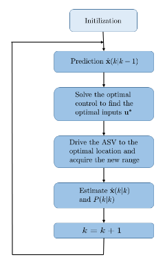
Fig. SO2.15. SBN architecture diagram
|
A similar approach was taken by IST team in the frame-work of Fisher information. Contrary to empirical observability Grammian, the Fisher information matrix (FIM) was used in a stochastic set-up. The objective is to maximize the FIM due to the well-known Cramer-Rao lower bound (CRLB). At the implementation phase, we used a sliding horizon window, in which planning, motion control, and estimation were carried out in sequence. At the planning phase, we solved an optimization problem of finding the optimal input for a number of samples, typically 6. Then the first optimal input was executed to drive the vehicle to the next optimal position, where a new measurement was taken. The overall system of SBN is shown in Fig. SO2.15., where is the state estimate, its associate covariance and the optimal control input. A more complete description was published in Moreno-Salinas (2016).
Regarding the estimator, the Extended Kalman Filter described in year 2 report was used, without any USBL measurements. To estimate the underwater vehicle position, it had access to both range and velocity vector measurements once every 6 seconds.
While assuming that the BUDDY vehicle was performing an arbitrary underwater mission, the surface vehicle has to position itself in order to maximize the range information that gets from him. For that an online planner was developed that every time there is a new range measurement, recalculated the trajectory to be tracked.
As our emphasis is on the accuracy of the range-based target localization, we resort to optimal control where the cost functional is the logarithm of the determinant of the Fisher information matrix (FIM). As the inverse of the FIM is a lower bound for the achievable covariance by any unbiased estimator, maximizing the FIM lowers the covariance, thereby improves the accuracy. To achieve this goal for the single-target scenario, we provide first provide optimal trajectories analytically.
The planner block in Fig. SO2.15. solves the optimal control problem. As a first it solves the optimal control problem to find the optimal sequence of inputs for the next six samples, that is, it provides optimal values for the piecewise constant body-speed and the heading. In the next step, we apply the first optimal speed and heading angle to the surface vehicle to drive to the optimal location to acquire the ranges. The process is repeated at this new optimal location.
SBN results are shown in the Figure SO2.16., where the underwater vehicle was performing a mission at 0.2 m/s (purple/pink dots). As one can see, in the beginning of the mission, the radius that the surface vehicle does around the underwater is bigger, due to the higher covariance of the estimator, reducing to an asymptotic value in the middle of the mission.
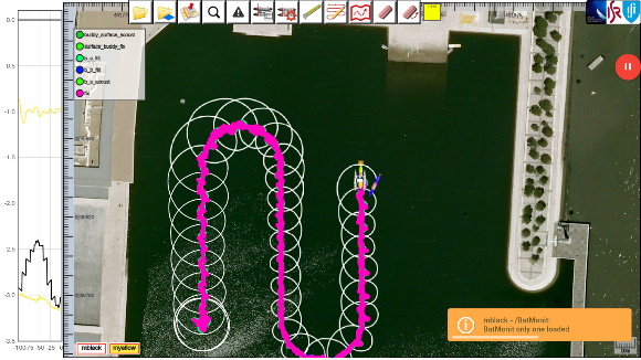
Fig. SO2.16. Single Beacon Navigation trials in Olivais dock
SO2.c. Execution of compliant BUDDY tasks initiated by hand gestures.
The aim of providing a compliant behaviour of the overall robotic system, with respect to the command issued by the diver, is made available through the development of an automatic selection system for the execution of the proper autonomous robotic tasks.
First of all, the basic CADDY functionalities have to be mapped into subsets of tasks that can be provided by the robotic platforms. In order to define the primitives-tasks matching, an additional high-level task set has to be defined as cross-interface between the primitives and robotic task sets.
A preliminary definition of the three sets is reported in Fig. SO2.17. where:
- functional primitives represent the macro-actions that the robotic platform has to carry out in order to support the diver operation and that are strictly related to the current functional mode (slave, guide, observer). The primitives are triggered by the recognized gestures;
- high-level logical tasks are the interface between the primitives and the operative task provided by robot. This logical task set is common in the overall architecture and will provide the required functionalities activating the proper low-level tasks that are currently made available by the employed robotic platform;
- low-level robotic tasks are the actual implemented autonomous functionalities on the target robot, e.g. speed regulators, heading and depth controller, etc. Depending on the low-level task availability, the CADDY compliant mission control system will properly select which high-level functionalities can be activated allowing, in turn, the enabling of the required primitives to fulfil the mission operations.
For the automatic selection, activation and inter-task conflict management, a Petri net based execution control system has been developed. The system is configured by means of a set of configuration files that specify, on one side, the capabilities of the robot in terms of autonomous tasks and, on the other side, the set of high level functionalities that the CADDY system has to provide for the diver support. A real-time Petri net engine models the logical interconnections among the tasks and primitives and, depending on the specific actions commanded by the diver, automatically handle the activation/deactivation of the proper task sets.
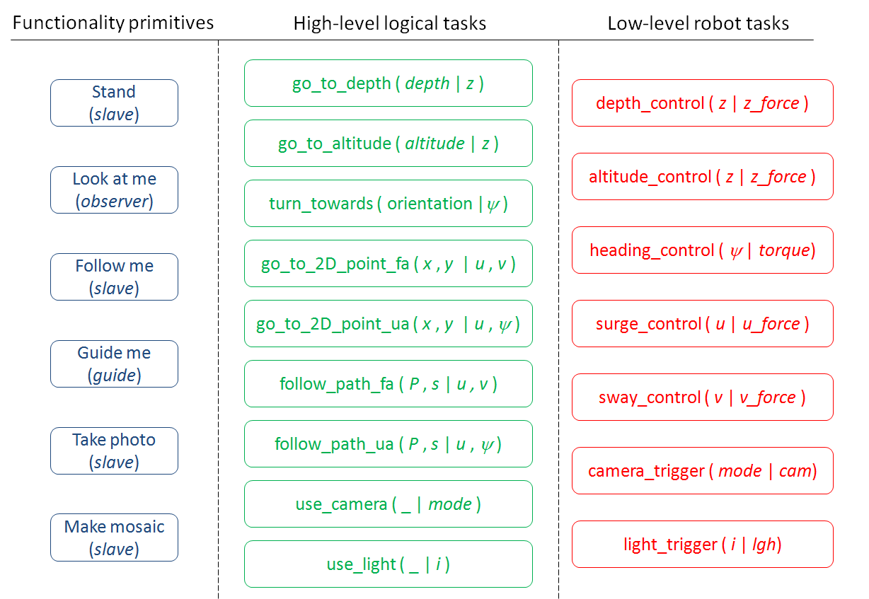
Fig. SO2.17. Primitives and tasks definition